Design of GIE
GIE (Graph Interactive Engine) is a system for interactive workloads on graphs, such as graph traversal and pattern matching. It provides a declarative query language for users to interact with the engine at the application layer. It also supports different computing engines at the runtime layer to meet various computing needs. GIE has two main design goals. One is to make it easy for users to use GIE with familiar query languages. The other is to make it easy to integrate different computing engines with GIE.
The Motivations
Graph data is a data structure that models the relationships between data. Compared with traditional relational data, it expresses relationships more intuitively and has inherent advantages in storage and computation. Therefore, graph queries play a very important role in massive data analysis. However, in practice, applying graph queries also faces some problems:
The diversity of query languages: Common graph query languages in business include Gremlin and Cypher. At the same time, there are also some customized extensions based on SQL for graph queries, some graph query languages developed by manufacturers themselves and the upcoming standardized GQL. Query language is the first entry point for business and has a strong stickiness for users. Once business people are familiar with a query language, the cost (learning cost, business shelving, etc.) of migrating to another language is very high. Therefore, the graph query platform needs to adapt to common query languages as much as possible.
The fragmentation of business scenarios: Different business scenarios have very different requirements for graph queries. Some common scenarios are business intelligence scenarios, high-throughput scenarios and their hybrid. In business intelligence scenarios, queries usually involve more hops of graph traversal and complex relational computations such as aggregation, deduplication and sorting. There is a higher demand for low latency of queries. In high-throughput scenarios, queries are relatively simple and only perform one or two hops of graph traversal. They value more the high throughput of queries, that is, to execute as many queries as possible in a unit time. In addition, hybrid scenarios hope to get a better trade-off between low latency and high throughput. The requirements for queries raised by different scenarios are fundamentally the requirements for the underlying computing engines. To meet these requirements, it is inevitable to introduce multiple computing engines

Figure 1. The current states of graph queries.
As shown in Figure 1, in order to support as many query languages as possible and adapt to various application scenarios, a realistic graph query system inevitably has to face an engineering implementation problem with a total of “M×N”, that is, for each of the “M” query languages to interface with each of the “N” computing engines. And for each of these implementations, a whole process including language parsing, query validation, query optimization and runtime implementation needs to be completed. The whole process is lengthy and complicated. It is not easy to do well in one of these implementations, let alone do well in all these “M×N” combinations.
The Architecture
Figure 2 shows the architecture of the GIE framework. It can be seen that the “M × N” fragmented engineering implementation in the original scene has been replaced by a unified GIE IR (Intermediate Representation) Layer. The GIE IR Layer is responsible for processing the two most core tasks in the graph query process, query verification and query optimization. Parsing for each language is completed in the corresponding client, and code generation for each execution engine is handled at the corresponding runtime. In this way, we only need to implement M parsers for M languages and N sets of code generation for N engines.
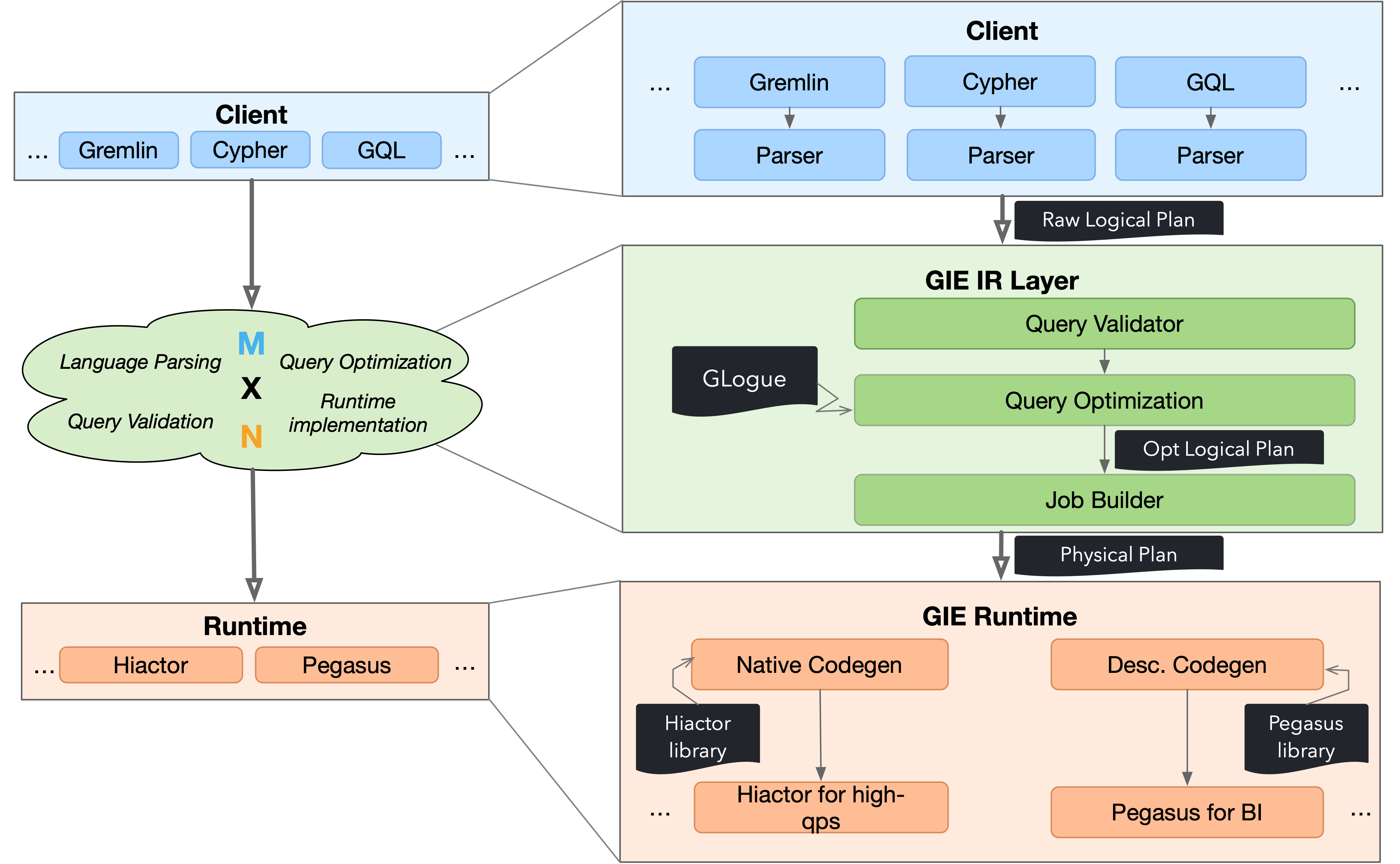
Figure 2. The architecture of GIE.
The original “M × N” engineering implementation can be replaced by this new “M+N” pattern. Even if M and N are not very large, such as in the case of “M = 2” and “N = 2”, the workload may not appear to be reduced, but it should be noted that:
The parts of query verification and optimization do not need to be implemented repeatedly. Based on our past engineering experience, these two parts of the work account for more than 80% of the entire query system implementation workload (measured by line of codes). This decoupling allows each engine module and query language module to be deployed throughout the query system like “building blocks”. Specifically, users can choose the corresponding “building blocks” of the upper-level language and lower-level engine when deploying the system, and then combine them with the compilation “building blocks” formed by the entire IR layer to assemble a query system that meets their language and computing needs.
Query Processing
Based on Figure 2, we briefly demonstrate the procedural of query processing in GIE.
Step 1: The user submits a graph query to the GIE engine. This query will be compiled by the
Parser of the corresponding language that we have registered in advance on the client-side into
a Raw Logical Plan consisting of IR operators. The IR operators include some relational algebra
operators inherited from relational database, such as Projection, Selection, Grouping,
Ordering, and operators related to graph operations, such as GetV, EdgeExpansion,
and PathExpansion. Among them, GetV represents obtaining vertices that meet the conditions
from the given edges, and EdgeExpansion and PathExpansion respectively represent expanding
edges and paths that meet the conditions from specific points (in fact, the meaning of “path”
is to continuously expand edges with specific hop counts).
Step 2: The Raw Logical Plan is submitted to the GIE server, and the query enters the GIE IR layer.
At this point, the Raw Logical Plan is checked for correctness through the query validator. On the one hand, it checks whether the connection between operators is legal. On the other hand, some operators contain expressions, such as a
Selectionoperator that includes “age + 1 > 10” as a predicate. For this expression, the query validator needs to get the type of age through the database schema and determine whether this type can complete subsequent arithmetic and logical operations. Once it fails to pass the query validator verification, the engine will immediately return the corresponding error message to the client.The validated query will enter the optimizer for optimization, which includes two aspects. Firstly, rule-based optimization (RBO) is performed, which includes common optimizations such as filter push-down and column slicing. Then, cost-based optimization (CBO) is performed, which uses the statistics provided by GLogue to estimate the cost of each part of the query. The optimizer will produce an optimized logical execution plan (Opt Logical Plan). Job Builder will build the physical execution plan based on the Opt Logical Plan. As the name suggests, the physical execution plan contains more “physical execution” information than the logical execution plan, including whether the underlying engine is distributed, whether the data is partitioned, and whether there are pre-registered algorithm libraries (such as shortest path calculation). Job Builder is responsible for appropriately inserting “shuffling” semantics into the logical execution plan to align the computation and storage partitions (if any) and for transforming operators into algorithm libraries, among other operations.
Step 3: Querying enters the execution layer. In the execution layer, GIE generates low-level execution code through code generation (Codegen) technology based on the physical execution plan according to the underlying execution engine. There are two types of Codegen here.
Native Codegen is mainly for high-throughput queries. In the native Codegen, the query needs to be pre-loaded into the system, and then the low-level native code will be generated and compiled automatically. It will be mounted to the system as a dynamic link library and returned to the user with a globally unique query ID. Users can use the query ID plus some query parameters for subsequent fast queries. Because in high-throughput scenarios, users’ queries are usually similar, only with different parameters, this can ensure high throughput of queries as much as possible.
Descriptive Codegen is mainly for low-latency queries. Since pre-compilation is required for native Codegen, this process may take several minutes, which is unacceptable in low-latency scenarios. Therefore, in descriptive Codegen, we register the implementation of each (physical) operator in advance with the engine, so that they can be compiled together with the engine. When the query comes, the system will select the registered operator according to the physical plan and assemble it into the final executable task.
Step 4: Finally, the query can be executed on the corresponding engine and the results are returned to the client.